
Safe Use: Beam Clamps
Safe Use of Beam Clamps
Beam clamps provide a simple and portable means of attaching a hoist to a runway or lifting beam. They should not be used on any beam other than those designed, tested and marked as a runway beam (or lifting beam), with the exception that they may be used on a beam forming part of a structure where a specific design check for this purpose has been made.
Selection
Beam clamps are available in two basic designs, the clip on type (FIG 1) and the more popular adjustable type (FIG 2).
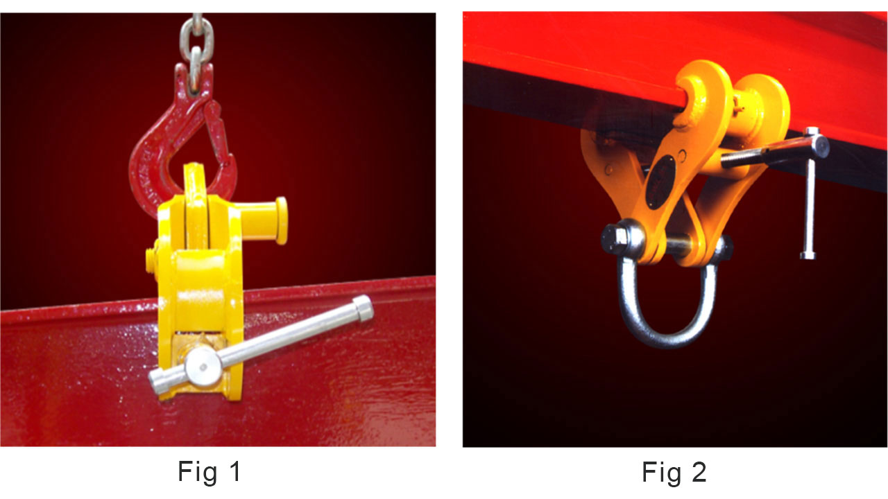
The main consideration when selecting the clamp is the required SWL, i.e. the load to be lifted plus the weight of the hoisting unit.
The width and thickness of the beam flange must also be considered and may well lead to the selection of a clamp in excess of the desired SWL to be compatible with the beam dimensions. The range and adjustability are indicated on the clamp's identification plate.
The majority of clamps are designed for 'in-line' use only, i.e. the line of force must be at right angles to the flange of the beam on which it is attached (see FIG 3). It is therefore important to ensure that for 'angled' applications, a clamp of suitable design is selected (see FIG 4).
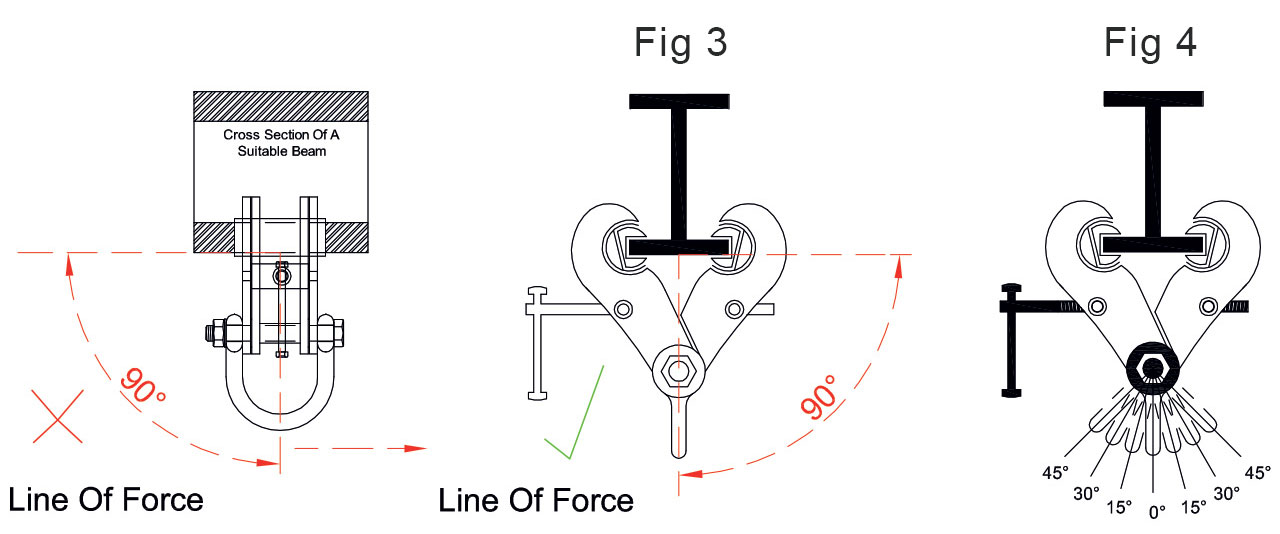
The tables below only apply to selected models of Riley's clamps. Stress calculations should be carried out by the user's engineering department for any/all steelwork from which the clamp will be suspended. The following work load limits and derations have been established specifically for most "S" type clamps and only apply in overhead beam use, i.e. do not apply if clamps are to be used for lifting beams. (The side load clamp 'USC range' has been specifically designed for this purpose.)
Reduction in Working Load Limits When Side Loads Applied
The following working load limits and derations apply specifically to most "S" type clamps when used overhead on a beam. They do not apply if clamps are being used for lifting beams the USC side load clamp range has been specifically designed for that purpose. Stress calculations should be carried out by the user's engineering department for any steelwork from which the clamp will be suspended.
| Model(s) | 0° No reduction |
0° – 15° –17% |
15° – 30° –34% |
30° – 45° –50% |
|---|---|---|---|---|
| S2A, S2AX, S5A | 3t | 2.5t | 2t | 1.5t |
| S3 | 4t | 3.3t | 2.6t | 2t |
| S3X, S3A, S6, S6A | 5t | 4.1t | 3.3t | 2.5t |
| S4 | 7t | 5.8t | 4.6t | 3.5t |
| S4S | 6t | 5t | 4t | 3t |
| S4A, S11 | 10t | 8.3t | 6.6t | 5t |
| S12, S14 | 15t | 12.4t | 10t | 7.5t |
| S15, S16 | 20t | 16.6t | 13.2t | 10t |
| S17, S18 | 25t | 20.7t | 16.5t | 12.5t |
| S19, S20 | 30t | 25t | 19.8t | 15t |